


- Register
- Wishlist (0)
- Shopping cart (0)
- You have no items in your shopping cart.
- Log in

SMD car timer switch relay 1-150 sec delay stop off 20A direct 12V out auto
Product Description and User Guide
Dimensions:
- Length: 23 mm
- Width: 16 mm
- Height: 18 mm
Power Supply:
- Voltage Range: 10 to 14 V DC
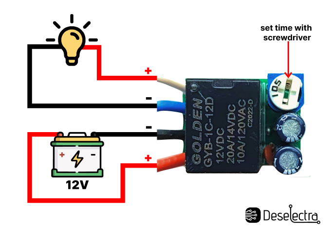
- Red Wire: 12V+
- Black Wire: 12V-
Output:
- Direct 12V 20A
- White Wire: 12V+
- Blue Wire: 12V-
Features:
- Time Adjustment: Using a trimmer. Rotate counterclockwise with a small screwdriver to increase the time.
- LED Indication: LED lights up when the relay is activated.
- Safety Recommendation: Place a 20A fuse on the red wire for protection.
Important Notes:
- Minimum Voltage: The timer will not function if the power supply is below 10V.
- Minimal Time Setting: If set to the minimal time, the relay will click upon powering the timer (this setting is not recommended).
- Output Voltage: The output has voltage; you can wire the load directly.
- High Current Loads: If using a load exceeding 20A, use a separate powerful relay after the timer.
Working Principle: When power is applied, the delay time starts, the LED diode lights up, and the output (white and blue wires) receives 12V. When the set time elapses, the relay is deactivated, and the output stops receiving 12V, even if the power is still on. Restarting the power supply repeats the cycle.
Application Example: The device, housed in a plastic box as shown in the picture, can be used to delay the activation of car lights. When the ignition is started, the timer will wait for the set time (0-150 seconds) before turning on the front lights, thus conserving the car battery. When the ignition is turned off, the lights will turn off immediately. The timer receives 12V from the ignition key contact, and the output should be wired to the front lights switch.
Wiring Diagram:
Power Supply:
- Connect the red wire to the 12V+ source (e.g., car battery positive terminal).
- Connect the black wire to the 12V- source (e.g., car battery negative terminal).
- For safety, place a 20A fuse on the red wire.
Output Connection:
- Connect the white wire to the load's 12V+ input.
- Connect the blue wire to the load's 12V- input.
Usage Instructions:
- Set the Delay Time: Adjust the trimmer with a small screwdriver. Rotate counterclockwise to increase the delay time.
- Power On: When the power is supplied, the delay time starts, and the LED lights up, indicating the relay is active.
- Wait for Activation: Once the set time elapses, the relay deactivates, and the output stops receiving 12V.
- Restart Cycle: To restart the cycle, cut off and reapply the power supply.
Safety Tips:
- Ensure all connections are secure.
- Do not exceed the specified load of 20A without using a separate relay.
- Always place a 20A fuse on the red power supply wire to prevent damage.
By following these instructions, you can effectively use this timer relay to manage delayed activation of car lights or other similar applications.