Chicken coop reverse polarity garage door gate opener controller module 12V 2A
Limited Time Offer!
Hurry, our best price won’t last long! Click to check out the exclusive deal: Click here to see the best price

User Guide: Electric Reverse Polarity Garage Door Gate Opener Controller Module (12V, 2A)
Overview
This controller module is designed to operate small 12V DC electric doors and gates, such as chicken coop doors, garage doors, and gate openers. It provides timed control for both opening and closing, with built-in polarity reversal to change motor direction.
Specifications:
- Power Supply: 12V DC with reverse polarity protection (min 4A adapter recommended)
- Output: Direct 12V DC, 2A max (wired with two white wires)
- Control Pulses: Can be triggered by positive (12V+) and negative pulses
- LED Indications:
- Green LED - Motor running in one direction (e.g., opening)
- Red LED - Motor running in the other direction (e.g., closing)
- Dimensions:
- Length: 39 mm
- Width: 34 mm
- Height: 16 mm
- Timer Adjustment: Adjustable by trimmer; rotate counterclockwise to increase the time
Wiring Instructions:
Power Connection:
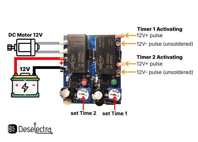
- Red Wire: Connect to 12V positive (+).
- Black Wire: Connect to 12V negative (−).
- Use a minimum 4A power adapter to prevent module restarts from voltage drops during motor start-up.
Motor Connection:
- White Wires: Connect directly to the motor (max 2A).
Control Input (Timer Start):
- Yellow Wires: Use to start the timers:
- One yellow wire for the positive 12V+ pulse (activates Timer 1).
- One yellow wire for the negative pulse (activates Timer 2).
- Yellow Wires: Use to start the timers:
Reverse Polarity Activation:
- When Timer 1 is triggered by a 12V+ pulse, the module supplies power in one direction to run the motor.
- When Timer 2 is triggered by a 12V- pulse, the module reverses polarity and supplies power in the opposite direction.
Operation Principle:
- Timer Activation:
- Timer 1: Upon receiving a 12V+ pulse, the motor starts running in one direction for the set duration, then stops.
- Timer 2: Upon receiving a 12V- pulse, the motor reverses and runs for the set duration, then stops.
Important Note:
- Use a powerful DC adapter (min 4A) to ensure stable operation without module resets, especially during motor startup.


